

Generator differential protection
Classification of generator differential protection
- The ratio braking differential protection is the main protection for the internal phase-to-phase short-circuit fault of the generator.
- The incomplete longitudinal differential protection is the main protection for the internal fault of the generator (or generator-transformer group), which can not only reflect various phase-to-phase short circuits inside the generator (or generator-transformer group), but also reflect the inter-turn short circuit and the opening of branch windings. Welding failure. The scalar product differential protection can be applied to generators, transformers, etc. as the main protection for internal faults.
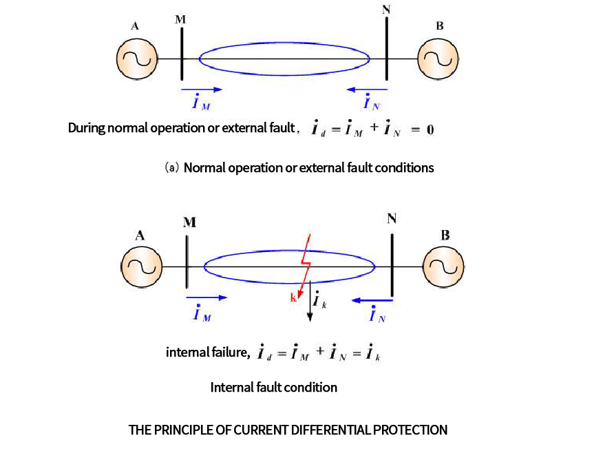
The principle of generator differential protection
Differential protection works by using Kirchhoff’s current theorem. When the generator is working normally or has a fault outside the area, it is regarded as an ideal generator, and the current flowing into the transformer is equal to the current flowing out (the converted current), and the difference is the same. The moving relay does not operate. When there is an internal fault of the generator, two sides (or three sides) provide short-circuit current to the fault point, the sum of the secondary currents felt by the differential protection is proportional to the fault point current, and the differential relay operates.
Circulating current differential protection works on the principle that the currents entering and leaving the protection zone are equal, any difference in these currents representing a fault in the protection zone. If the current transformer s is connected,E.g
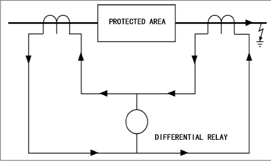
As a protection device, differential relays provide feedback from current transformers located at two different locations in the system. The differential relay compares the currents and if there is a difference it indicates a fault in the protected area. These devices are often used to protect generator or motor coils.
Defects in the insulation of the stator windings or connections can lead to severe damage to the windings and stator core
The extent of damage depends on the magnitude of the accident current and the duration of the accident. Protection is used to limit the extent of damage to control the cost of repairs. For primary power generation equipment, it is also necessary to quickly disconnect from the power system to maintain the stability of the system. For generators with rated output above 1MVA, the most common method is to use generator differential protection. Once a serious overcurrent accident occurs, this unit protection method can quickly determine the detected winding fault in time.
The range of protection determined by the position of the current transformer should overlap with the protection range of other equipment, such as busbars or step-up transformers. In cases where differential protection is not used,
(1) When the differential protection secondary circuit and current transformer circuit are changed or checked.
(2) The relay protection personnel measure the current phasor and differential pressure of the differential loop.
(3) One-phase disconnection or open circuit of the differential protection transformer.
(4) There are obvious abnormalities in the differential circuit.
(5) Malfunction tripping.
(6) Generators with relatively small rated capacity
(7) Differential protection is generally not used below 35KV
